咨询电话:17350880093 咨询电话:17350880093
  手机:17350880093

— 产品中心 —
 全国免费客服电话 17350880093
 邮箱:sales@fyplc.cn
手机:17350880093
电话:17350880093
地址:福建省漳州市龙文区朝阳北路1号办公楼205室

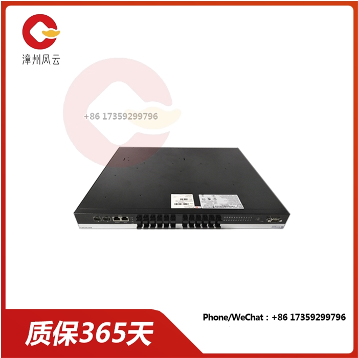
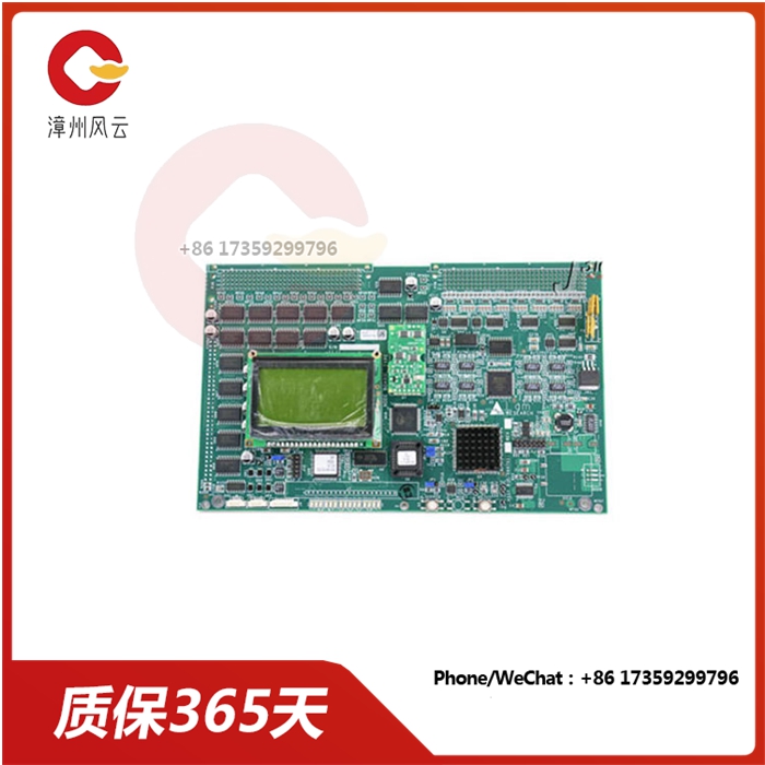
TRICONEX 4119A 增强型智能通信模块品牌TRICONEX操作系统DCS输出频率60hzHz特点增强型物料编码4119A系统能力强大颜色黑色重量2.3千克加工定制否是否进口是端口个数4个原产地美国系列TRICON端口隔离500 VDC可售卖地全国用途智能通信模块TRICONEX 4119A 增强型智能通信模块扫描技术当PLC投入运行后,其工作过程一般分为三个阶段,即输入采样、用户程序执行
产品详情
TRICONEX 4119A 增强型智能通信模块
TRICONEX 4119A 增强型智能通信模块
扫描技术
当PLC投入运行后,其工作过程一般分为三个阶段,即输入采样、用户程序执行和输出刷新三个阶段。完成上述三个阶段称作一个扫描周
期。在整个运行期间,PLC的CPU以一定的扫描速度重复执行上述三个阶段。
1、输入采样阶段在输入采样阶段
PLC以扫描方式依次地读入所有输入状态和数据,并将它们存入I/O映象区中的相应得单元内。输入采样结束后,转入用户程序执行和输出
刷新阶段。在这两个阶段中,即使输入状态和数据发生变化,I/O映象区中的相应单元的状态和数据也不会改变。因此,如果输入是脉冲信号,则该脉冲信号的宽度大于一个扫描周期,才能在任何情况下,该输入均能被读入。
2、用户程序执行阶段
在用户程序执行阶段,PLC总是按由上而下的顺序依次地扫描用户程序(梯形图)。在扫描每一条梯形图时,又总是先扫描梯形图左边的由各
触点构成的控制线路,并按先左后右、先上后下的顺序对由触点构成的控制线路进行逻辑运算,然后根据逻辑运算的结果,刷新该逻辑线圈在系统RAM存储区中对应位的状态;或者刷新该输出线圈在/O映象区中对应位的状态;或者确定是否要执行该梯形图所规定的特殊功能指令。
即,在用户程序执行过程中,只有输入点在/O映象区内的状态和数据不会发生变化,而其他输出点和软设备在/O映象区或系统RAM存储区内的状态和数据都有可能发生变化,而且排在上面的梯形图,其程序执行结果会对排在下面的凡是用到这些线圈或数据的梯形图起作用相反,排在下面的梯形图,其被刷新的逻辑线圈的状态或数据只能到下一个扫描周期才能对排在其上面的程序起作用。
在程序执行的过程中如果使用立即/O指令则可以直接存取I/O点。即使用I/O指令的话,输入过程影像寄存器的值不会被更新,程序直接从
I/O模块取值,输出过程影像寄存器会被立即更新,这跟立即输入有些区别。
TRICONEX 4119A 增强型智能通信模块
Scanning technique
When the PLC is put into operation, its working process is generally divided into three stages, namely input sampling, user program execution and output refresh three stages. Completing these three stages is called a scan cycle
Time. During the entire operation period, the PLC's CPU repeats the above three stages at a certain scanning speed.
1, input sampling stage in the input sampling stage
The PLC successively reads all input status and data in a scanning manner and stores them in the corresponding cell in the I/O map area. After the input sampling is finished, it is transferred to the user program for execution and output
Refresh phase. In both phases, even if the input state and data change, the state and data of the corresponding unit in the I/O map area will not change. Therefore, if the input is a pulse signal, the width of the pulse signal is greater than one scan cycle, so that the input can be read in any case.
2. User program execution stage
In the execution phase of the user program, the PLC always scans the user program in sequence from top to bottom (ladder diagram). When scanning each ladder, it always scans the left side of the ladder first
A control line composed of contacts, and carry out logical operations on the control line composed of contacts in the order of first left and then right, first up and then down, and then refresh the status of the corresponding bit of the logic coil in the RAM storage area of the system according to the results of logical operations; Or refresh the state of the corresponding bit of the output coil in the /O map area; Or determine whether to execute the special function instructions specified in the ladder diagram.
That is, during the execution of the user program, only the status and data of the input point in the /O image area will not change, while the status and data of other output points and software devices in the /O image area or the system RAM storage area are likely to change, and the status and data are listed above. In contrast to the following ladder diagram where these coils or data are used, the status or data of the refreshed logic coils can only be useful to the program above them until the next scan cycle.
I/O points can be accessed directly if immediate /O instructions are used during program execution. Even if the I/O instruction is used, the value of the input process image register is not updated, and the program is directly removed
I/O module values, the output process image register is updated immediately, which is somewhat different from immediate input.
相关推荐

服务热线