 手机:17350880093
— 产品中心 —
 全国免费客服电话 17350880093
 邮箱:sales@fyplc.cn
手机:17350880093
电话:17350880093
地址:福建省漳州市龙文区朝阳北路1号办公楼205室
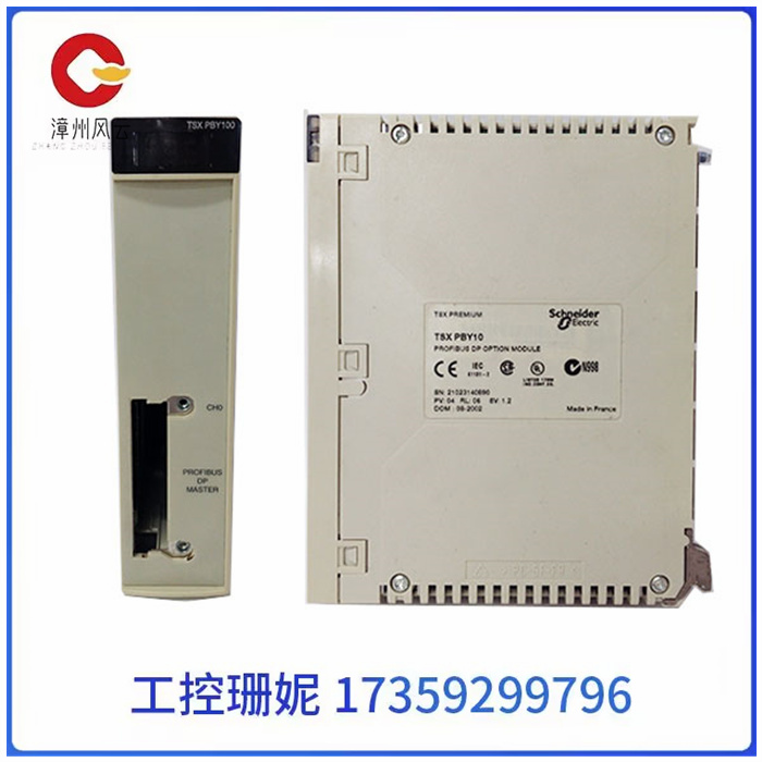
TSXPBY10 PLC/DCS模块品牌Schneider产品特性卡件模块是否进口否产地美国加工定制否工作电压220V输出频率50kHz产品认证系统备件卡件模块系列系统备件卡件模块物料编码系统备件卡件模块可售卖地全国型号TSXPBY10TSXPBY10 PLC/DCS模块设计特点:必须从手动MFT按钮1和按钮2上均取二对常开触点分别接入交流和直流回路。删除了MFT复位硬操按钮回路,只能由MFT软操
产品详情
TSXPBY10 PLC/DCS模块
TSXPBY10 PLC/DCS模块
设计特点:必须从手动MFT按钮1和按钮2上均取二对常开触点分别接入交流和直流回路。删除了MFT复位硬操按钮回路,只能由MFT软操复位。目的是确保BMS主DPU正常后才能复位MFT信号。MFT三取二接点信号是由DPU控制柜中三块DO卡件输出的MFT1、MFT2、MFT3三对信号经硬跳闸回路中交流继电器扩展回路而产生,12对触点分两组分别接入交流和直流跳闸回路中,6对触点构成MFT三取二逻辑信号。
这套逻辑回路设计周全、严密,充分考虑到了硬件和软件冗余,既防误动又防拒动。设计重点考虑:
(1)手动MFT按钮1和按钮2应设置五对触点分别接入BMS的DI卡件,交流跳闸回路,直流跳闸回路,SOE点,按钮点灯指示。接线施工中应避免混淆220VAC、110VDC、48VDC三种配电电源。
(2)SCS所属四个DPU机柜分别接收BMS四个D块卡件输出的四个MFT硬接线信号,没有采用网上传输点。
(3)MFT交流和直流两回路继电器动作输出接点与各子系统DPU的DO卡件端子板继电器动作接点要一一对应并接正确。
(4)明确MFT跳闸输出信号内容。

TSXPBY10 PLC/DCS模块
Design features: Two pairs of normally open contacts must be taken from the manual MFT button 1 and button 2 to connect to the AC and DC circuits respectively. The MFT reset hard operation button loop is removed and can only be reset by MFT soft operation. The purpose is to ensure that the main DPU of the BMS is normal before resetting the MFT signal. The MFT two-out-of-three contact signal is generated by the three pairs of MFT1, MFT2 and MFT3 signals output by the three DO cards in the DPU control cabinet through the AC relay expansion loop in the hard trip circuit. The 12 pairs of contacts are connected to the AC and DC trip circuits in two groups respectively, and the 6 pairs of contacts constitute the MFT two-out-of-three logic signal.
The design of this logic loop is comprehensive and strict, taking full account of hardware and software redundancy, which is both anti-error and anti-rejection. Key design considerations:
(1) Manual MFT button 1 and button 2 should be set up five pairs of contacts respectively connected to the DI card of BMS, AC trip circuit, DC trip circuit, SOE point, button lighting indication. Avoid mixing 220VAC, 110VDC and 48VDC distribution power supplies during wiring construction.
(2) The four DPU cabinets belonging to SCS receive the four MFT hardwired signals output by the four D-block BMS respectively, and do not use the network transmission point.
(3) The action output contact of the MFT AC and DC two-loop relays and the action contact of the DO card terminal board of the DPU of each subsystem should correspond one by one and be connected correctly.
(4) Clarify the content of the MFT trip output signal.
相关推荐