 手机:17359299796
— 产品中心 —
 全国免费客服电话 17359299796
 邮箱:A3669372910@163.com
手机:17359299796
电话:17359299796
地址:福建省漳州市龙文区朝阳北路1号办公楼205室
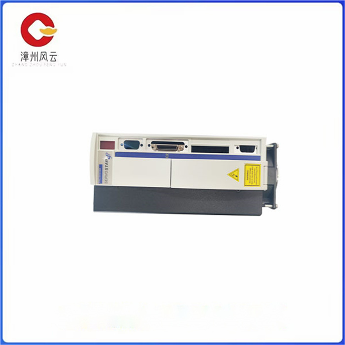
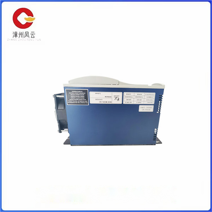
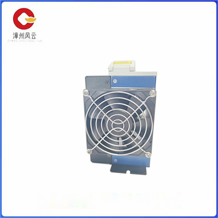
CP310250科尔摩根伺服驱动器REV功率品牌KOLLMORGE科尔摩根加工定制否支持系统伺服驱动器规格PRD-P310250D-55工作温度-10-20C(
产品详情
CP310250 主要由热电偶、运算扩大器。将温度转化成处理器可辨认的数字信号。
本规划的温度收集电路如图2所示,在P6口的1、3引脚接热电偶传感器的正端,2、4引脚接热电偶传感器的负端。热电偶收集到信号后经C00、 C10(高频滤波电容)将高频杂波滤除,再经27L2(低频小信号扩大器)将信号扩大,其中R64与R63的和与R65的比值即为U3B的扩大倍数,同理,R60与R62的和与R61的比值为U3A的扩大倍数。扩大后再经C01和C11将高频杂波滤除,该信号被传到ARM7,经其内部AD转化器将模仿电压信号转化成处理器可辨认的数字信号。当热电偶传感器探头部分的温度发生改变时,热电偶传感器两头的电压也按一定份额对应发生改变,然后该电压信号经 27L2扩大,再经ARM内部AD将模仿量转化成数字量,ARM处理器得到数字量后便知道现在的温度。当然要想准确测温仅有热电偶测温模块是不行的。
因为热电偶传感器有一个缺陷,它测的温度是探头与冷端之间的温度差,也就是说若仅用上述电路测温,则只有在冷端温度为零点的情况下测得的温度才是*准确的,冷端的温度与零点的温差越大,测得的温度数据越不准确。而本规划中焊台加热的同时,热电偶冷端温度会改变,从而造成了测温不准确。为了处理上述问题,特别增加了DS18B20作为补偿,在工业上称为补正系数修正法。
本规划选用ARM7作为主控芯片,主要因其性价比高、资源丰富、作业安稳牢靠。它带有32kB的片内Flash程序存储器和 8kB的片内静态RAM;128位宽度接口/可完成高达70MHz作业频率;10位A/D转化器供给8路输入;2个32位守时计数器和2个16位守时计数器;多达32个通用IO口,可接受5V电压;多个串行接口,包括2个UART、2个I2C总线、SPI和具有缓冲作用和数据长度可变功用的SSP;多达13个边沿、电平触发的外部中止管脚;一个可编程的片内PLL可完成为70MHz的CPU操作频率等等。
3ARM*小体系中,11.0592M的晶振和两个20pF电容为体系供给安稳的作业频率,然后再经ARM内部锁相环倍频使其作业频率可达70MHz。图中的U1为,它为体系供给安稳的复位电路,同时为体系供给了256字节的可读写的E2PROM,使体系存储掉电不丢掉数据空间。


The CP310250 is mainly composed of thermocouples and operational amplifiers. Converts the temperature into a digital signal that the processor can recognize.
The planned temperature collection circuit is shown in Figure 2. Pin 1 and pin 3 of port P6 are connected to the positive end of the thermocouple sensor, pin 2 and pin 4 are connected to the negative end of the thermocouple sensor. After the thermocouple collects the signal, the high-frequency clutter is filtered by C00 and C10 (high-frequency filter capacitor), and then the signal is expanded by 27L2 (low-frequency small signal amplifier), where the ratio of R64 and R63 and R65 is the expansion multiple of U3B, similarly, the ratio of R60 and R62 and R61 is the expansion multiple of U3A. After enlargement, the high frequency clutter is filtered through the C01 and C11, and the signal is transmitted to the ARM7, and the AD converter inside the ARM7 converts the simulated voltage signal into a digital signal that the processor can recognize. When the temperature of the probe part of the thermocouple sensor changes, the voltage at both ends of the thermocouple sensor also changes according to a certain proportion, and then the voltage signal is expanded by 27L2, and then the imitation quantity is converted into a digital quantity by the AD inside the ARM, and the ARM processor knows the current temperature after getting the digital quantity. Of course, if you want to measure the temperature accurately, only the thermocouple temperature measurement module is not possible.
Because the thermocouple sensor has a defect, the temperature it measures is the temperature difference between the probe and the cold end, that is, if the temperature is measured only with the above circuit, the temperature measured is the most accurate only when the cold end temperature is zero, the greater the temperature difference between the cold end temperature and the zero point, the more inaccurate the temperature data measured. However, when the welding table is heated in this plan, the temperature of the cold end of the thermocouple will change, resulting in inaccurate temperature measurement. In order to deal with the above problems, DS18B20 is specially added as compensation, which is called the correction coefficient correction method in industry.
ARM7 is selected as the main control chip in this plan, mainly because of its high cost performance, rich resources, stable and reliable operation. It comes with 32kB of on-chip Flash program memory and 8kB of on-chip static RAM. 128-bit width interface/can complete up to 70MHz operating frequency; 10-bit A/D converter provides 8 inputs; 2 32-bit punctuality counters and 2 16-bit punctuality counters; Up to 32 general purpose IO ports, can accept 5V voltage; Multiple serial interfaces, including 2 UART, 2 I2C buses, SPI and SSP with buffering and variable data length functions; Up to 13 edge-triggered external stop pins; A programmable on-chip PLL can be accomplished with a CPU operating frequency of 70MHz, and so on.
In the 3ARM* small system, the 11.0592M crystal oscillator and two 20pF capacitors provide a stable operating frequency for the system, and then the ARM internal phase-locked loop frequency is doubled to make its operating frequency up to 70MHz. U1 in the figure is, it provides a stable reset circuit for the system, and at the same time provides 256 bytes of readable and writable E2PROM for the system, so that the system does not lose data space after power failure.

相关推荐