咨询电话:17359299796 咨询电话:17359299796
  手机:17359299796

— 产品中心 —
 全国免费客服电话 17359299796
 邮箱:A3669372910@163.com
手机:17359299796
电话:17359299796
地址:福建省漳州市龙文区朝阳北路1号办公楼205室

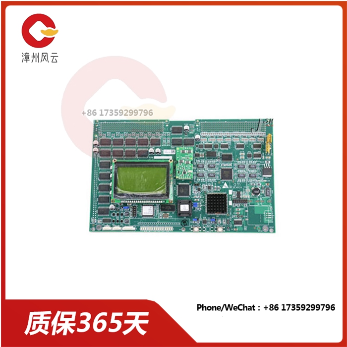
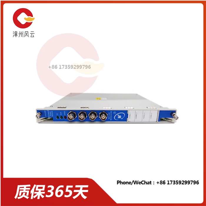
安康 DS3800HPBC 平行线路缓冲板 有一个模块化连接器品牌GE加工定制否操作温度(-22F to +150F).湿度95%, noncondensing.硬件RS422接口指示灯驱动显示通道(s) 上面的LED处于警戒状态。储存温度(-40F to +185F).重量0.82 kg通道更新率1 second, typical能量功耗4.6 watts max.功耗10.5瓦通信USB-B面
产品详情
Product description
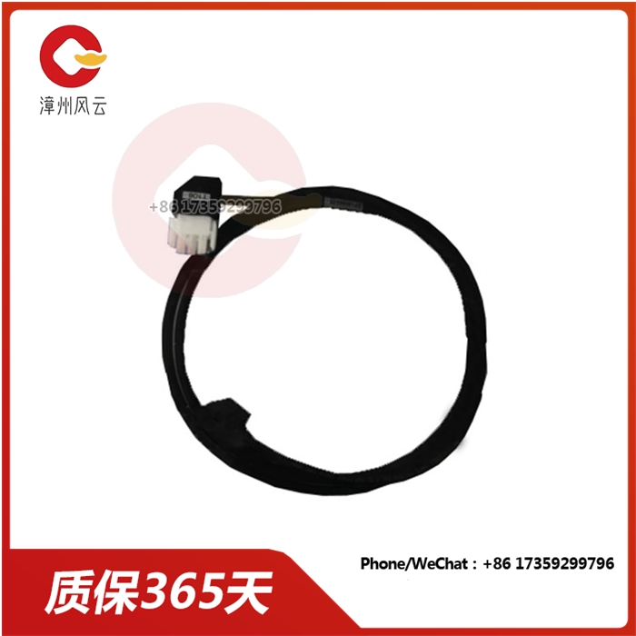
The GE Parallel Line buffer board DS3800HPBC is designed for quick installation in drives. The board has a modular connector at one end and a fixed rod at the other end. The GE parallel line buffer board DS1HPBC also has 3,800 red indicator leds and one amber LED, visible from the front of the board. The board is also equipped with 2 jumpers and multiple capacitors.
Another component on the board is a transistor-to-transistor logic (TTL) device. It serves as the interface logic between integrated circuits. The drive operator verifies that the drive is fully functioning and monitors the drive's operation. Operators are also responsible for multiple drives and other equipment. Another function is to verify that the motherboard in the drive is normal and keep the motherboard functional. One way is to look at the leds on the board. When the board is running, the LED on the board is visible.
When the red LED lights up, it means that an error has occurred and the motherboard function has stopped. When the red LED lights up, first power off the drive and perform a motherboard reset. The signals received and sent by the circuit board sometimes lose their correct order. A reset can help solve the problem. Lift the board from the handle, then remove the board from the connector on the back of the motherboard. Then, plug the circuit board into the modular connector again and lock it into place using a fixed tie rod.
Product description
The GE Parallel Line buffer board DS3800HPBC is designed for quick installation in drives. The board has a modular connector at one end and a fixed rod at the other end. The GE parallel line buffer board DS1HPBC also has 3,800 red indicator leds and one amber LED, visible from the front of the board. The board is also equipped with 2 jumpers and multiple capacitors.
Another component on the board is a transistor-to-transistor logic (TTL) device. It serves as the interface logic between integrated circuits. The drive operator verifies that the drive is fully functioning and monitors the drive's operation. Operators are also responsible for multiple drives and other equipment. Another function is to verify that the motherboard in the drive is normal and keep the motherboard functional. One way is to look at the leds on the board. When the board is running, the LED on the board is visible.
When the red LED lights up, it means that an error has occurred and the motherboard function has stopped. When the red LED lights up, first power off the drive and perform a motherboard reset. The signals received and sent by the circuit board sometimes lose their correct order. A reset can help solve the problem. Lift the board from the handle, then remove the board from the connector on the back of the motherboard. Then, plug the circuit board into the modular connector again and lock it into place using a fixed tie rod.
相关推荐

服务热线