 手机:17359299796
— 产品中心 —
 全国免费客服电话 17359299796
 邮箱:A3669372910@163.com
手机:17359299796
电话:17359299796
地址:福建省漳州市龙文区朝阳北路1号办公楼205室
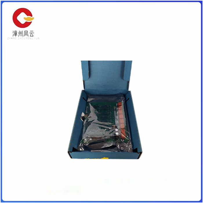
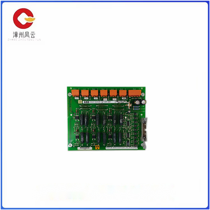
LTC391AE01 ABB 用晶闸管移相全桥电路实现励磁品牌ABB内部变量变适用范围广是否进口是报警功能报输入电压110特色服务售后系统内存52电源电压220物料编码123015工作温度25其他功能辅助额定电压220断开容量12可售卖地全国型号LTC391AE01LTC391AE01 ABB 用晶闸管移相全桥电路实现励磁1 总体结构HIEE401782R0001 LTC391AE01励磁系统总
产品详情
1 总体结构
HIEE401782R0001 LTC391AE01励磁系统总体结构框图如1所示。包括零电压零电流开关(ZVZCS)DC/DC移相变换全桥电路、驱动电路、灭磁电路、励磁电压、电流调理电路、DSP控制电路、键盘及显示电路、跳闸保护电路等。
三相交流电源经接触器加到三相整流模块变为直流。直流主回路供电加入400 ms的软启动,以防高的电压冲击,Ci为输入滤波电容,并起到提高功率因数的作用。主电路软启动接通后,DSP根据键盘设定的一种调节方式,在接受到起励指令后,输出规定励磁电压,通过DSP对励磁参数测量实现励磁电流的闭环控制。保护电路中设计输入过压、欠压保护、过流保护和过热保护。
2 主电路工作原理
图2为ZVZCS变换器的主电路图,并联电容C1,C2和变压器的漏感Lk一起实现超前臂开关管VQ1,VQ2的ZVS。通过控制有源钳位开关VQC来实现滞后臂开关管VQ3,VQ4的ZCS。
图3为ZVZCS变换器的一个开关周期的主要工作波形。VQ1和VQ2在C1,C2和Lk作用下实现ZVS。T1时刻,变压器的初级电压Vab下降为零,此时使VQC导通,使钳位电容上电压Vcc反射到初级的Lk上,与因电流减小而产生的电动势的方向正好相反,因此,使初级电流ILk迅速减小到零,而且由于串入VD1,VD2使变压器初级续流时不会在反方向形成环流,从而使滞后臂开关管VQ3,VQ4实现零电流导通和关断。

1 Overall Structure
HIEE401782R0001 LTC391AE01 excitation system overall structure block diagram is shown in 1. Including zero voltage zero current switch (ZVZCS)DC/DC phase-shift conversion full bridge circuit, drive circuit, magnetic circuit, excitation voltage, current conditioning circuit, DSP control circuit, keyboard and display circuit, trip protection circuit, etc.
The three-phase AC power supply is added to the three-phase rectifier module through the contactor to become DC. The DC main circuit power supply adds 400 ms soft start to prevent high voltage shock, Ci is the input filter capacitor, and plays a role in improving the power factor. After the main circuit is switched on, the DSP outputs the specified excitation voltage according to an adjustment mode set by the keyboard after receiving the excitation instruction, and realizes the closed-loop control of the excitation current through the measurement of the excitation parameters by DSP. Design input overvoltage protection, undervoltage protection, overcurrent protection and overheating protection in the protection circuit.
2 Working principle of the main circuit
Figure 2 is the main circuit diagram of the ZVZCS converter. The parallel capacitors C1, C2 and the leakage sensing Lk of the transformer together realize the ZVS of the leading arm switching tube VQ1 and VQ2. By controlling the active clamp switch VQC, the ZCS of the lagging arm switch tube VQ3 and VQ4 are realized.
Figure 3 shows the main operating waveform of a switching cycle of the ZVZCS converter. VQ1 and VQ2 achieve ZVS under the action of C1, C2 and Lk. At T1, the primary voltage Vab of the transformer drops to zero. At this time, the VQC is switched on, so that the voltage Vcc on the clamping capacitor is reflected to the primary Lk, which is opposite to the direction of the electromotive force generated by the reduction of current. Therefore, the primary current ILk is rapidly reduced to zero. VD2 makes the transformer do not form a circulation in the opposite direction when the primary current is continued, so that the lagging arm switch tube VQ3 and VQ4 can realize zero current on and off.

| ABB DCS | QUINT-PS/1AC/24DC/20 | YXM187D 3ASD510001C16 | 张力控制放大器 |
| ABB DCS | QUINT-PS/1AC/24DC/3.5 | YXE152A/YT204001-AF/YXE 152A | 卡件 |
| ABB DCS | CP-C.1 24/10.0 | YXE152A YT204001-AF | I/O架子 |
| ABB DCS | CP-C.1 24/5.0 | YT272001-AG | 机器人主板 |
| ABB DCS | G81A 019, 10KV,30A | YPN104C/3AFE81014477 | 控制板 |
| ABB DCS | TP3-2131A230M KIT | YPN104C 3AFE81014477 YPM106E YT204001-FN | CPU模块 |
| ABB DCS | LG 7928.97 | YPN104C 3AFE81014477 | 二极管 |
| ABB DCS | CT-APS.22S | YPM106E/YT204001-FN ABB | 整流桥接口板 |
| ABB DCS | AF30-30-00-13 | YPM105A/YT204001-BH | 卡件模块 |
| ABB DCS | MS132-6.3 | YPM102E YT204001-FL | 调试电缆 |
| ABB DCS | MS132-12 | YPK111A/YT204001-HH | 变频器模块 |
| ABB DCS | MS132-25T | YPK107E/3ASD489301A410 | 触摸屏 |
相关推荐