 手机:17350880093
— 产品中心 —
 全国免费客服电话 17350880093
 邮箱:sales@flplc.cn
手机:17350880093
电话:17350880093
地址:福建省漳州市龙文区朝阳北路1号办公楼205室
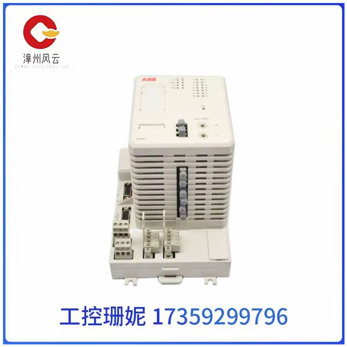
ABB PM825 3BSE010796R1全新原装现货自动化控制系统电源处理器模块品牌ABB功率360批号PM8253BSE010796R1特色服务无电源电压24电源电流240处理器速度6数量10可售卖地全国用途控制器类型模块型号PM8253BSE010796R1ABB PM825 3BSE010796R1全新原装现货自动化控制系统电源处理器模块1、初始化参数 在接线之前,先初始化参数。
产品详情
ABB PM825 3BSE010796R1全新原装现货自动化控制系统电源处理器模块
ABB PM825 3BSE010796R1全新原装现货自动化控制系统电源处理器模块
1、初始化参数 在接线之前,先初始化参数。 在控制卡上:选好控制方式;将PID参数清零;让控制卡上电时默认使能信号关闭;将此状态保存,确保控制卡再次上电时即为此状态。 在伺服电机上:设置控制方式;设置使能由外部控制;编码器信号输出的齿轮比;设置控制信号与电机转速的比例关系。一般来说,建议使伺服工作中的最大设计转速对应9V的控制电压。比如,松下是设置1V电压对应的转速,出厂值为500,如果你只准备让电机在1000转以下工作,那么,将这个参数设置为111。
2、接线 将控制卡断电,连接控制卡与伺服之间的信号线。以下的线是必须要接的:控制卡的模拟量输出线、使能信号线、伺服输出的编码器信号线。复查接线没有错误后,电机和控制卡(以及PC)上电。此时电机应该不动,而且可以用外力轻松转动,如果不是这样,检查使能信号的设置与接线。用外力转动电机,检查控制卡是否可以正确检测到电机位置的变化,否则检查编码器信号的接线和设置。
3、试方向 对于一个闭环控制系统,如果反馈信号的方向不正确,后果肯定是灾难性的。通过控制卡打开伺服的使能信号。这是伺服应该以一个较低的速度转动,这就是传说中的“零漂 ”。一般控制卡上都会有抑制零漂的指令或参数。使用这个指令或参数,看电机的转速和方向是否可以通过这个指令(参数)控制。如果不能控制,检查模拟量接线及控制方式的参数设置。确认给出正数,电机正转,编码器计数增加;给出负数,
电机反转转,编码器计数减小。如果电机带有负载,行程有限,不要采用这种方式。测试不要给过大的电压,建议在1V以下。如果方向不一致,可以修改控制卡或电机上的参数,使其一致。
4、抑制零漂 在闭环控制过程中,零漂的存在会对控制效果有一定的影响,最好将其抑制住。使用控制卡或伺服上抑制零飘的参数,仔细调整,使电机的转速趋近于零。由于零漂本身也有一定的随机性,所以,不必要求电机转速绝对为零。
5、建立闭环控制 再次通过控制卡将伺服使能信号放开,在控制卡上输入一个较小的比例增益,至于多大算较小,这只能凭感觉了,如果实在不放心,就输入控制卡能允许的最小值。将控制卡和伺服的使能信号打开。这时,电机应该已经能够按照运动指令大致做出动作了。

ABB PM825 3BSE010796R1全新原装现货自动化控制系统电源处理器模块
1. Initialize parameters Initialize parameters before connecting cables. On the control card: select the control mode; Clear PID parameters to zero; Turn off the enable signal by default when the control card is powered on. Save this state to ensure that it is in this state when the controller card is powered on again. On the servo motor: set the control mode; Settings enable external control; Gear ratio of encoder signal output; Set the proportional relationship between the control signal and the motor speed. In general, it is recommended that the maximum design speed in the servo operation corresponds to the control voltage of 9V. For example, Panasonic is set 1V voltage corresponding to the speed, the factory value is 500, if you are only ready to let the motor work below 1000 RPM, then set this parameter to 111.
2, wiring will power off the control card, connect the signal line between the control card and the servo. The following lines must be connected: the analog output line of the control card, the enable signal line, the encoder signal line of the servo output. After checking that the wiring is correct, the motor and control card (and PC) are powered on. At this time, the motor should not move, and can be easily rotated with external force, if not, check the setting and wiring of the enable signal. Turn the motor with an external force, check whether the control card can correctly detect the change in the position of the motor, otherwise check the wiring and setting of the encoder signal.
3, test direction for a closed-loop control system, if the direction of the feedback signal is not correct, the consequences are certainly disastrous. Turn on the enable signal of the servo via the control card. This is where the servo should turn at a lower speed, which is the legendary "zero drift". Generally, there will be instructions or parameters on the control card to suppress zero drift. Use this command or parameter to see if the speed and direction of the motor can be controlled by this command (parameter). If it cannot be controlled, check the parameter Settings of analog wiring and control mode. Confirm that the positive number is given, the motor is turning forward, and the encoder count is increased; Give a negative number,
Motor reverse rotation, encoder count reduced. If the motor has a load and limited travel, do not use this method. Do not give too much voltage to the test, it is recommended to be below 1V. If the direction is not consistent, you can modify the parameters on the control card or the motor to make them consistent.
4, inhibit zero drift In the closed-loop control process, the existence of zero drift will have a certain impact on the control effect, it is best to suppress it. Using the control card or the parameters on the servo to suppress zero drift, carefully adjust the speed of the motor to approach zero. Since the zero drift itself also has a certain randomness, it is not necessary to require the motor speed to be absolutely zero.
5, establish a closed-loop control again through the control card to release the servo enable signal, input a small proportional gain on the control card, as for how small, this can only be felt, if it is really not assured, enter the control card can allow the minimum value. Turn on the enable signals for the control card and the servo. At this time, the motor should have been able to roughly make movements in accordance with the motion instructions.
相关推荐