 手机:17359299796
— 产品中心 —
 全国免费客服电话 17359299796
 邮箱:A3669372910@163.com
手机:17359299796
电话:17359299796
地址:福建省漳州市龙文区朝阳北路1号办公楼205室
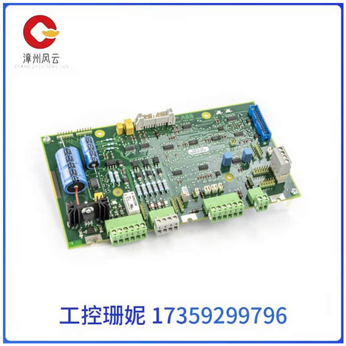
DSTS106 3BSE007287R1 触发脉冲发生器卡品牌ABB销售范围全国安装方式直接上机可售卖地全国类型模块型号DSTS106DSTS106 3BSE007287R1 触发脉冲发生器卡DSTS106 3BSE007287R1卡件DCS模块TC561V2 3BSE022179R1 TC560V2 3BSE022178R1使用以下步骤标定模块。此中使用的输入包程序仅用作示例。建议预热5分钟
产品详情
DSTS106 3BSE007287R1 触发脉冲发生器卡
DSTS106 3BSE007287R1 触发脉冲发生器卡
DSTS106 3BSE007287R1卡件DCS模块TC561V2 3BSE022179R1 TC560V2 3BSE022178R1使用以下步骤标定模块。此中使用的输入包程序仅用作示例。建议预热5分钟校准前。
电压表连接图步骤操作1要接近两个装饰罐,拆下位于前面板上的两个螺钉和标签模块,如上面的微调罐位置图所示。注:顶部微调罐调整范围的总大小(满标度)。
底部微调罐调整零偏移量刻度。2打开模块手柄,露出连接器和端子。3在任何通道中安装输入包,并连接适当的信号源频道请参阅下面的电压表连接图。4将输入信号应用于代表零信号的选定通道(当使用模拟,V输入包,低带宽,0至+10V(AS-5B31003A)。
上编程面板观察所选通道的B875输入。调整零校准控制(R29)读取0000。5施加输入信号,使输出在满量程的80-90%之间。使用9.375 V如果使用模拟、V输入包、低带宽、0至+10V(AS--5B31003A)。结果读数应设置为0F00十六进制或3840十进制刻度校准控制(R57)。
6重复前两步,直到读数在零和接近满刻度时正确点。7校准完成后,断开电压表,将连接件恢复至原始状态状态,关闭模块手柄,并更换覆盖装饰罐的前标签。

DSTS106 3BSE007287R1 触发脉冲发生器卡
DSTS106 3BSE007287R1 card DCS module TC561V2 3BSE022179R1 TC560V2 3BSE022178R1 Use the following steps to calibrate the module. The input packages used in this article are for example purposes only. Recommended preheat 5 minutes before calibration.
Voltmeter Connection Diagram Step Operation 1 To approach the two decorative tanks, remove the two screws and label modules located on the front panel, as shown in the trimmer tank position diagram above. Note: The top trimmer tank adjusts the total size of the range (full scale).
Bottom trimmer tank adjusts zero offset scale. 2 Open the module handle to expose the connector and terminal. 3 Install the input package in any channel and connect the appropriate signal source channel. See the voltmeter connection diagram below. 4 Apply the input signal to the selected channel representing the zero signal (when using analog, V input packets, low bandwidth, 0 to +10V (AS-5B31003A).
The upper programming panel watches the B875 input for the selected channel. Adjust the zero calibration control (R29) to read 0000. 5 Apply the input signal so that the output is between 80-90% of full scale. Use 9.375V If using analog, V input packet, low bandwidth, 0 to +10V (AS--5B31003A). The resulting reading should be set to 0F00 hexadecimal or 3840 decimal scale Calibration control (R57).
6 Repeat the first two steps until the reading is correctly pointed at zero and near full scale. 7 After calibration, disconnect the voltmeter, restore the connector to its original state, close the module handle, and replace the front label covering the decorative tank.
相关推荐