 手机:17359299796
— 产品中心 —
 全国免费客服电话 17359299796
 邮箱:A3669372910@163.com
手机:17359299796
电话:17359299796
地址:福建省漳州市龙文区朝阳北路1号办公楼205室
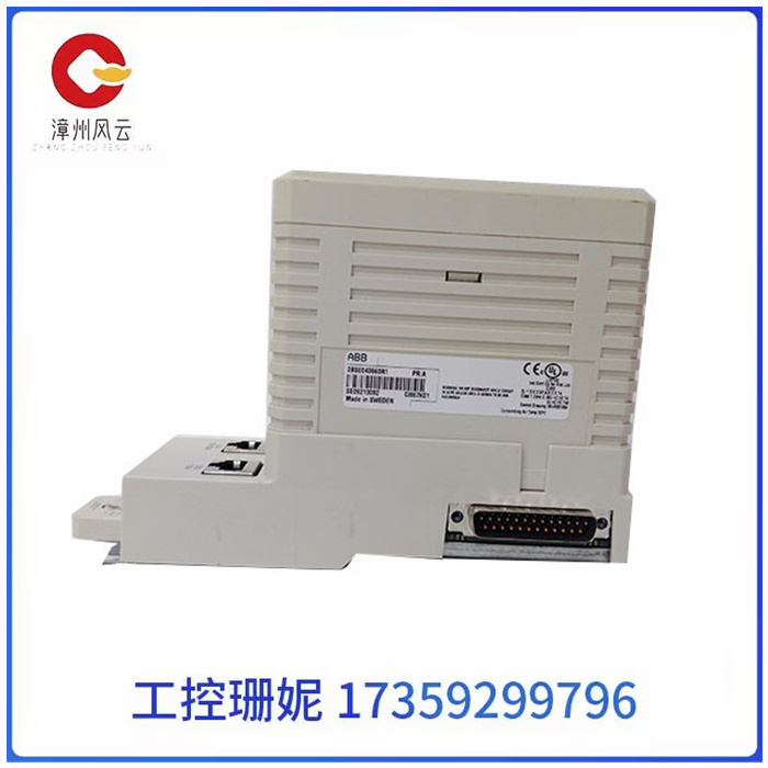
ABB CI867K01 继电器 3BSE043660R1 模块 AI610 输入输出用途通信模块加工定制否支持系统PLC DCS规格26*33*37型号CI867K01品名通信模块订货号3BSE043660R1形状方形重量26功率2700电压220V功能强大频率50/60HZ颜色标准色系统环境常温特点智能控制品牌ABBABB CI867K01 继电器 3BSE043660R1 模块 AI610
产品详情
ABB CI867K01 继电器 3BSE043660R1 模块 AI610 输入输出
ABB CI867K01 继电器 3BSE043660R1 模块 AI610 输入输出
(一)分析被控对象并提出控制要求
详细分析被控对象的工艺过程及工作特点,了解被控对象机、电、液之间的配合,提出被控对象对PLC控制系统的控制要求,确定控制方案,拟定设计任务书。
(二)确定输入/输出设备
根据系统的控制要求,确定系统所需的全部输入设备(如:按纽、位置开关、转换开关及各种传感器等)和输出设备(如:接触器、电磁阀、信号指示灯及其它执行器等),从而确定与PLC有关的输入/输出设备,以确定PLC的I/O点数。
(三)选择PLC
PLC选择包括对PLC的机型、容量、I/O模块、电源等的选择,详见本章第二节。
(四)分配I/O点并设计PLC外围硬件线路
1.分配I/O点
画出PLC的I/O点与输入/输出设备的连接图或对应关系表,该部分也可在第2步中进行。
2.设计PLC外围硬件线路
画出系统其它部分的电气线路图,包括主电路和未进入可编程控制器的控制电路等。
由PLC的I/O连接图和PLC外围电气线路图组成系统的电气原理图。到此为止系统的硬件电气线路已经确定。

ABB CI867K01 继电器 3BSE043660R1 模块 AI610 输入输出
(1) Analyze the controlled objects and put forward control requirements
Analyze the process and working characteristics of the controlled object in detail, understand the cooperation between the machine, electricity and hydraulic of the controlled object, put forward the control requirements of the controlled object on the PLC control system, determine the control plan, and formulate the design task book.
(b) Determine the input/output device
According to the control requirements of the system, determine all the input equipment required by the system (such as: buttons, position switches, transfer switches and various sensors, etc.) and output equipment (such as: contactors, solenoid valves, signal indicators and other actuators, etc.), so as to determine the input/output equipment related to PLC to determine the PLC I/O points.
(3) Select PLC
PLC selection includes the selection of PLC model, capacity, I/O module, power supply, etc., as detailed in Section 2 of this chapter.
(4) Allocate I/O points and design PLC peripheral hardware lines
1. Assign I/O points
Draw the connection diagram or correspondence table between the PLC I/O points and the input/output devices, which can also be done in Step 2.
2. Design PLC peripheral hardware circuit
Draw the electrical circuit diagram for the rest of the system, including the main circuit and the control circuit that does not enter the programmable controller.
The electrical schematic diagram of the system is composed of PLC I/O connection diagram and PLC peripheral electrical circuit diagram. So far the hardware electrical wiring of the system has been determined.
相关推荐